In previous blog posts and bylines shared by our team, we’ve discussed the wide range of applications for LiDAR technology. It’s not a question of whether LiDAR will pervade industries like agriculture, mining, smart cities, shuttles, and delivery vehicles, it’s a matter of when. As technology managers within these sectors dip their toes into LiDAR and begin to evaluate the offerings of each provider, our team here at Innoviz pulled together a list of key technological features to look for when selecting a LiDAR supplier.
Range matters, including the short-range
The ability to see objects on the road far away is a major factor when choosing a LiDAR, which is why the maximum digital limit of the InnovizPro has now increased from 150 meters to 600 meters. While the link budget and detection capability for a given target remain unchanged, we can now detect returns from different laser pulse sequences with some clever signal processing. This allows high reflectivity objects, like roadway signs and construction safety equipment, to be visible up to 600 meters away.
Many fleet operators have started to deploy LiDAR-equipped autonomous shuttles where pedestrian detection is vital. This safety-critical application for shuttles with fixed urban routes and geofenced operations is at the heart of public acceptance. Many spinning LiDAR sensors deployed in such shuttles provide a valid detection of an object only beyond half or one meter. Some sensors provide a valid detection only beyond two meters. These limitations on minimum range detection often require shuttle perception developers to supplement the spinning LiDAR with a separate short-range 3D or 2D line-scanning LiDAR, increasing cost and complexity for integration. The InnovizPro now detects obstacles down to 20 centimeters, allowing shuttles to install and use the same sensor for short- and long-range needs.
Solid-state is the best state
Beam steering approaches inside LiDAR sensors can either be mechanical or solid-state. Spinning LiDAR is the most widely available mechanical option and generates its field of view (FOV) by spinning large parts of the sensor, typically including optics, lasers, detectors, and supporting electronics. Spinning LiDAR sensors have been pervasive due to their availability, but in fact, are more prone to failure than their solid-state counterparts. The weak points of moving components inside a spinning LiDAR are exposed in common driving scenarios. Vibration, mechanical shock, temperature changes, humidity changes, etc. cause those weak points to fail. The laser channels become misaligned which leads to increased noise and reduced depth accuracy in the point-cloud. Also, the sensor becomes prone to optical interference. Eventually, the sensor fails — warranty return rates with spinning sensors are notoriously high.
On the other hand, solid-state beam steering is significantly more reliable. For example, our InnovizPro leverages a silicon-based, frictionless MEMS (Micro-Electro-Mechanical Systems) mirror to steer its lasers. The optics, lasers, detectors, and all the electronics are fixed and the MEMS is used to scan the laser where we want to look. This makes the sensor innately more resilient to the environmental conditions of roadways, farmlands, construction sites, and mines.
Now, consider the world of smart cities where connected infrastructure is equipped with LiDAR sensors to provide real-time data to city operators. This connected infrastructure, typically outdoors, requires a 24/7 stream of visual data, which means the LiDAR must be continuously running. City development projects using spinning LiDAR sensors are left to deal with high costs of repair and replacement due to their failure rate. Looking beyond the development stage, spinning sensors are simply not suitable for long-term installation in rough environments and varying weather conditions, whereas, the InnovizPro MEMS architecture can reduce operational and maintenance costs for LiDAR-based smart city applications due to robustness and longevity.
Contiguous pixels enable complete visibility
Most LiDARs work by illuminating small portions of the landscape and focusing a detector at that same area to measure the time-of-flight of the laser pulse. Depending on the sensor, each of these points can be collected individually or several at a time. When you collect many of these points very quickly (hundreds of thousands or millions of times per second), you get a point-cloud covering the FOV of the sensor. In most LiDAR sensors, and particularly in spinning sensors, there are large gaps between these points (see comparison image below).
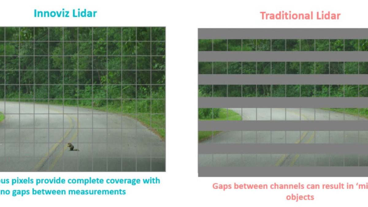
Contiguous vs non-contiguous pixels inside a LiDAR sensor compared.
Practically speaking, these gaps mean that the sensor is never illuminating, and therefore never seeing, parts of the FOV. Thus, the LiDAR data may not provide important details or may not show small objects that are in the FOV. This is a critical shortcoming in building a safe AV perception system. There should not be data gaps in the point-cloud data provided to the ‘vehicle brain’ that is making driving decisions. The InnovizPro has a unique detector and optical architecture with contiguous pixels, meaning the laser illuminates the entire FOV and the point-cloud data has zero gaps. At all times and in every single frame, InnovizPro illuminates and captures all objects in its FOV given the object is large enough to generate a return.
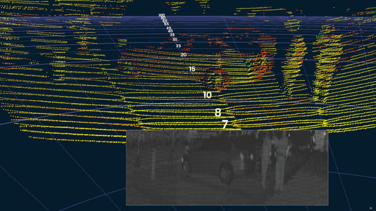
2D calibrated reflectivity reconstruction in real-time shows no data gaps in the entire FOV of an InnovizPro sensor.
LiDAR sensors with uniform resolution offer ‘point-and-shoot’ ease
InnovizPro provides a uniform resolution of 0.2° horizontally by 0.45° vertically across a 73° by 20° FOV. In the language of spinning sensors, it’s equivalent to 44 lines (see comparison image below).
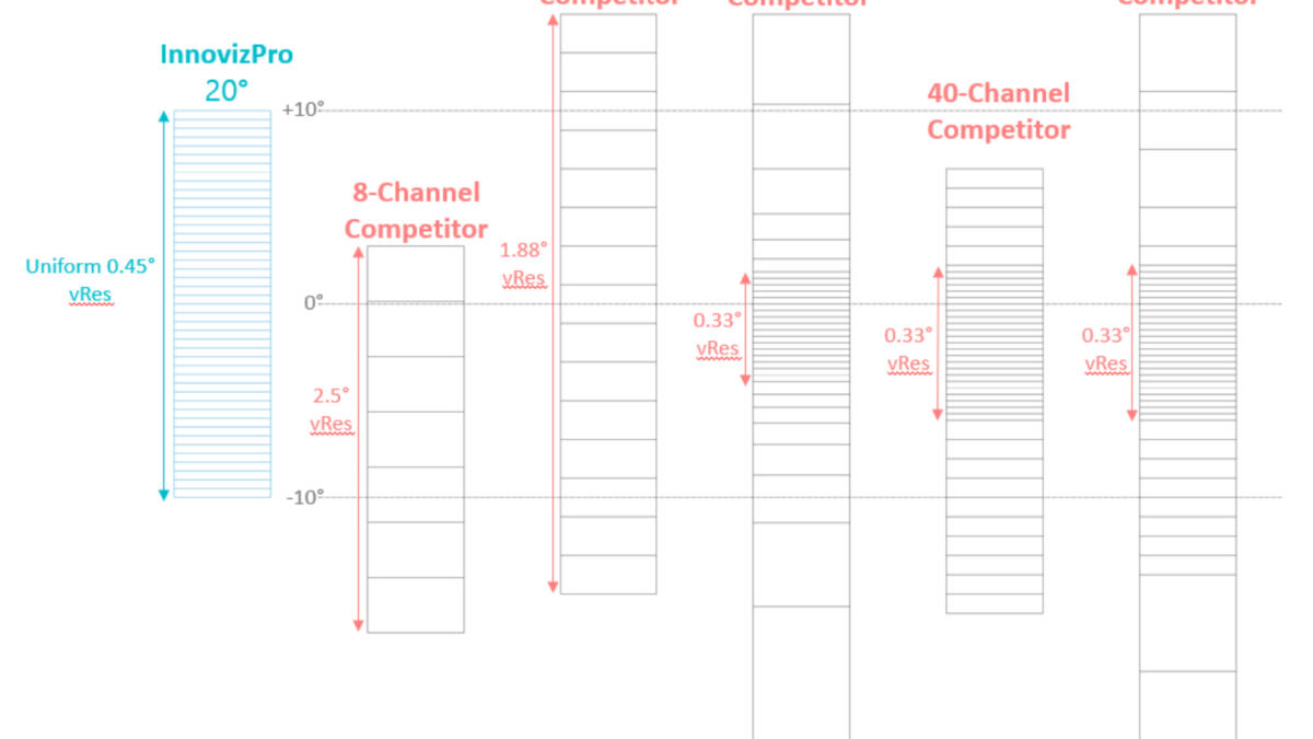
Scaled location of each channel in the vertical FOV comparing InnovizPro to traditional mechanical LiDAR sensors.
It is important to note that these lines are uniformly distributed in the vertical FOV and the ‘point-and-shoot’ form-factor of the sensor does not have horizon limitations, meaning the sensor can be installed and aimed wherever pixel density is needed. The InnovizPro can be tilted up to look for landmarks in aiding localization or tilted down to aid object detection and obstacle avoidance, while outputting point-cloud data with uniform resolution and no data gaps. A spinning LiDAR is typically installed parallel to the horizon in order to maintain usefulness of the 360° FOV, but as soon as it’s angled up or down, a large portion of the FOV ‘shoots at the sky’ and wastes points.
With InnovizPro’s modular design, multiple sensors can be distributed around the vehicle to achieve a customized 360° point-cloud with uniform resolution and high pixel density in each direction. The ‘point-and-shoot’ form factor allows easy installation strategy for mounting height and tilt angle. In addition, a uniform resolution point-cloud without data gaps increases accuracy in object classification software providing high value for perception developers.
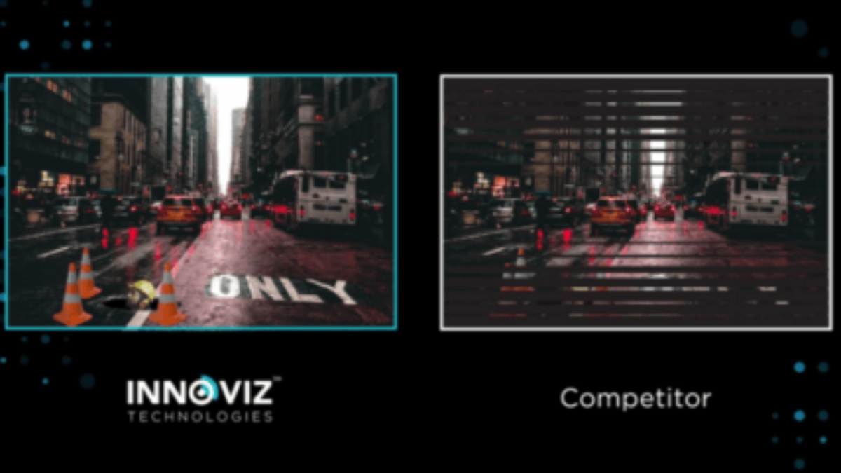
Solutions with MEMS minimize interference
MEMS-based laser beam steering offers significantly reduced optical interference from light sources including sunlight or other LiDAR sensors. A spinning LiDAR has multitude of detectors that create wide open optical cavities. These cavities increase active areas where stray light is picked up, resulting in noise and optical interference. Such interference appears as false positives resulting in error-prone or inaccurate perception or mapping due to noise in the point-cloud. Alternately, InnovizPro sees the world ‘through a straw’ due to its carefully designed optical path which mitigates interference. The detector looks through a narrow passage which is precisely pointed at the area illuminated by the laser. This means that any stray photons not perfectly in line with the object being measured will either not enter the ‘straw’ or will strike the inner walls to be absorbed or deflected. Therefore, the InnovizPro avoids confusion from other light sources to deliver a cleaner and more stable point-cloud with low noise and low jitter giving the system better data to build a safer and more reliable perception model.
Final Thoughts
At Innoviz, we see a wide set of applications for the InnovizPro, ranging from safety critical urban fixed route shuttles to high-reliability industrial use-cases. We have engineered this reliable sensor to meet high-performance specifications from 20 centimeters, up to a long 600-meter range. As we take the product to market, we look forward to helping our customers with world-class engineering support and opening new applications for LiDAR technology.
Also read: Demoing our Automotive-Grade InnovizOne Lidar Sensor